When changing the PLC communication method from Serial to Ethernet, follow the steps below in TOP Design Studio (TDS).
Step 1. Open Project Options
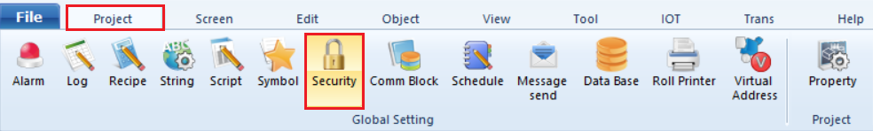
-. In TDS, go to [Project] - [Property].
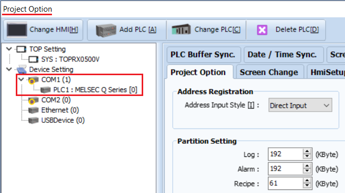
-. The [Project Option] window will appear.
Step 2. Check Current Device Setting
On the left side under [Device Setting], you will see [PLC1] assigned to the Serial COM1 port.
To change this PLC to Ethernet, you must first add a PLC to the Ethernet port.
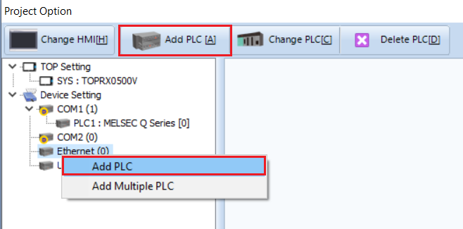
-. Right-click the Ethernet port to add a PLC, or click the [Add PLC] button at the top.
Step 3. Add a PLC to the Ethernet Port
Add the same PLC as assigned to COM1.
Configure the alias name and Ethernet communication parameters as required (interface, protocol, PLC IP address, etc.).
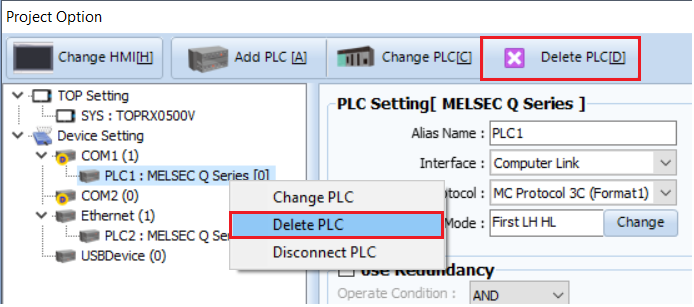
Step 4. Delete the Serial PLC
After adding the PLC to the Ethernet port, right-click the PLC assigned to COM1 to delete PLC (or use the [Delete PLC] button).
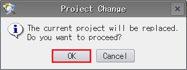
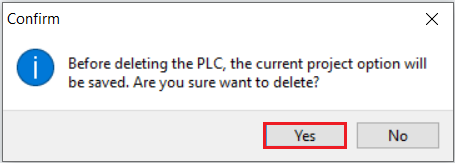
A Confirm window will appear.
Step 5. Select Replacement PLC
Click [YES].
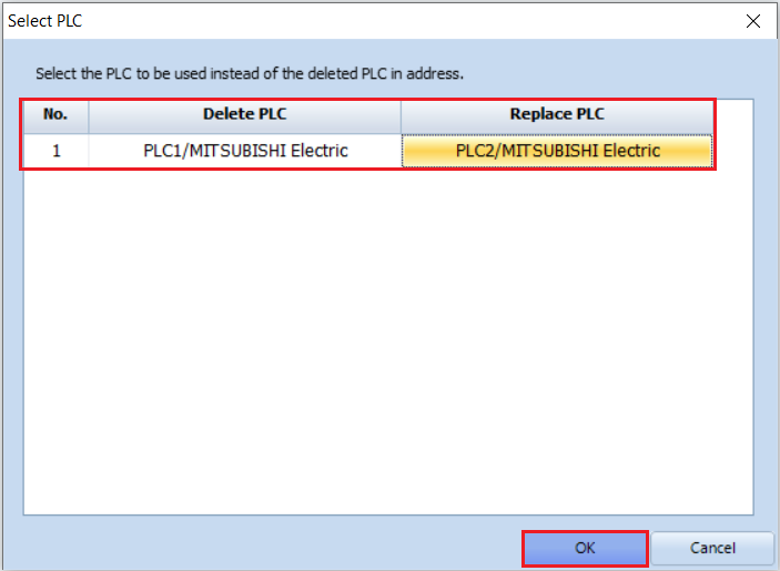
A [Select PLC] pop-up will appear asking you to select a replacement PLC.
Choose the PLC you just added to the Ethernet port and click [OK].
The system will automatically update the PLC addresses from the COM1 port to the Ethernet port.
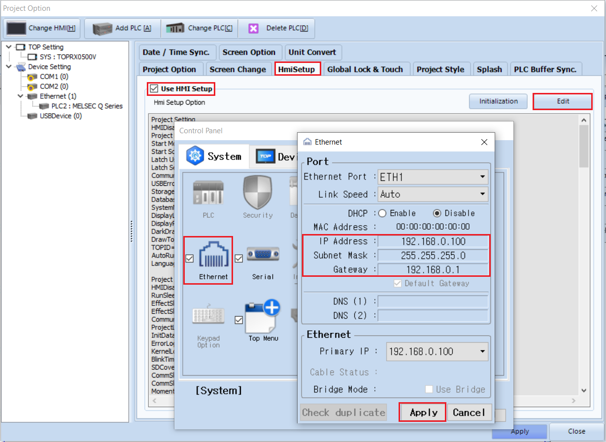
Step 6. Configure HMI Ethernet Settings
Go to [Project] - [Property] - [HmiSetup] - [Edit] - [Ethernet] and configure the TOP IP address.
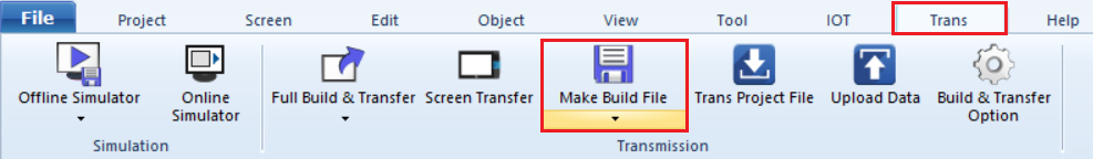
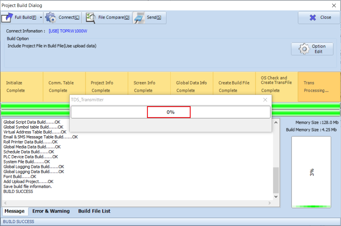
Step 7. Build and Transfer the Project
Go to [Trans] - [Full Build & Transfer] to download the project to the TOP.